
How to Prepare Production Drawings Accurately

A drawing can look complete on screen and still leave a fabricator guessing. A missing bend radius, unclear material callout or dimension taken from the wrong edge can cause delays, unnecessary rework and parts that do not assemble as intended. Knowing how to prepare production drawings means translating design intent into clear, controlled manufacturing instructions.
For custom acrylic work, that instruction set needs to account for more than the finished shape. Material behaviour, cutting method, folding sequence, adhesive joints, hardware and visual finish all affect the result. The objective is not to create the most detailed drawing possible. It is to provide the exact information required to manufacture, inspect and repeat the component with confidence.
Start with the manufacturing outcome
Before opening CAD, define what the part must do. Is it a retail display that needs a premium polished edge? A clear machine guard that must fit existing equipment? An illuminated sign face with precise cut-outs? Or a repeatable component for a larger production run?
This context determines which dimensions are critical, where tolerances belong and which manufacturing method is appropriate. A decorative acrylic panel may allow more flexibility than an interlocking assembly. A one-off prototype can be used to validate assumptions, while a production component needs information that supports consistent repetition.
A good drawing package separates requirements into three practical areas: the part geometry, the material and finish specification, and the assembly or installation requirements. When these are mixed together without hierarchy, errors become more likely.
Use clear views, datums and dimensions
Every production drawing should show the part in views that make its form unambiguous. For a flat laser-cut panel, a plan view may be sufficient. For a folded, thermoformed or welded acrylic component, include front, side and sectional views where needed. An isometric view can help communicate overall intent, but it should support the drawing rather than replace dimensioned orthographic views.
Dimension from stable reference points, known as datums. In practice, this means selecting edges, centre lines or faces that are meaningful to the way the part will be cut, formed or assembled. Avoid chain dimensioning across a part where accumulated variation could affect the final location of holes, slots or mating features.
For example, if a clear acrylic display tray has a logo cut-out and mounting holes, locate both from the same nominated datum edge. Do not dimension the logo from one side and the holes from another unless that relationship is deliberate. The fabricator and quality team should be able to inspect the component using the same references shown in the drawing.
Dimensions should state finished requirements. If a feature is created before folding, make that clear. If a formed profile is critical, include the final formed dimensions and, where relevant, the fold line or forming reference required to achieve them.
Apply tolerances where they matter
Not every dimension needs a tight tolerance. Over-specifying tolerances increases manufacturing time and cost, particularly on large acrylic parts where material movement and forming processes must be considered.
Apply tighter tolerances to features that affect fit, alignment, hardware or function. These may include hole centres, interlocking tabs, rebates, slot widths and the overall dimensions of a part fitting into an existing frame. Cosmetic features and non-mating external dimensions may be able to carry a more practical general tolerance.
The right tolerance depends on the feature, material thickness, process and production quantity. Laser cutting, CNC routing, acrylic folding and thermoforming each have different capabilities and considerations. If a tolerance is commercially or functionally critical, discuss it with the manufacturer before locking in the drawing.
Specify the acrylic, not just the thickness
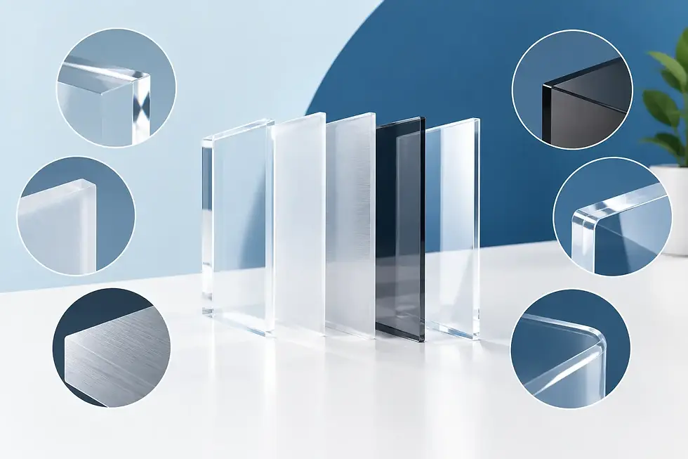
Calling out “3 mm clear acrylic” is often not enough. Acrylic sheets vary by grade, colour, finish and manufacturing method, and these differences can affect appearance, machining, bonding and formed performance.
State the exact material requirement: cast or extruded acrylic where relevant, nominal thickness, colour or tint, gloss or matte surface, opacity, translucency and any special properties such as UV resistance or impact performance. If colour matching is essential for branded retail work or signage, nominate a recognised material reference or provide an approved sample.
Protective film requirements are also worth noting. A part may need film retained through cutting and fabrication to protect presentation surfaces, then removed before final assembly. If both faces must remain visually clean, make that expectation explicit.
For visible work, nominate the required edge finish. A saw-cut, laser-cut, routed, polished or flame-polished edge can each be appropriate, but they do not produce the same result. The choice should reflect the design, budget and performance requirement. A polished edge may be essential on a premium display, while a concealed internal component may not justify the additional finishing time.
Make fabrication operations explicit
Production drawings become far more reliable when they identify how the component is intended to be made, especially where the process affects the final geometry or appearance.
For folded acrylic, show fold lines, fold direction, finished angles and internal or external bend requirements. Acrylic does not behave like sheet metal. Heat line bending needs allowance for material thickness, bend position and potential visual changes at the fold. A simple note such as “fold 90 degrees” may be insufficient if orientation or critical finished dimensions are not shown.
For welded or bonded assemblies, identify joint locations and the required visual standard. Is the joint structural, watertight or primarily cosmetic? Does it need to be clear and bubble-free in a customer-facing display? Should excess adhesive be removed from visible faces? These details influence preparation, fixturing and finishing.
For CNC-cut or laser-cut components, identify countersinks, counterbores, tapped holes, engraving, etching and through-cuts clearly. Use standard symbols where appropriate, but do not rely on symbols alone if the component has an unusual requirement. A concise note that states the feature, depth and finished purpose can prevent misinterpretation.
Include hardware and assembly information
A fabricated part rarely exists in isolation. If it uses screws, stand-offs, hinges, magnets, LEDs, printed graphics or metal inserts, show the relevant interfaces and nominate the hardware clearly.
Where hardware is client-supplied, provide the manufacturer with accurate product details or physical samples early. Nominal screw sizes do not always tell the full story, particularly where head diameter, clearance, thread engagement or fixing sequence affects the design.
Assembly drawings are particularly useful for multi-part displays, signage and installations. They should show part numbers, quantities, orientation and the relationship between components. An exploded view can communicate sequence efficiently, while section details can clarify concealed fixings, rebates and bonded joints.
If the installation environment affects the design, include that information. Wall substrate, access for fixing, clearances around electrical elements and transport constraints can all change how a component should be fabricated. A display that works in a drawing may be difficult to install if the fixing points are inaccessible after assembly.
Control revisions and supply usable files
A production drawing is a controlled document, not a static illustration. Include a clear drawing number, revision identifier, issue date, project name and approval status. When a change is made, identify exactly what changed. Sending revised files without revision control is one of the fastest ways to create duplicate work or manufacture superseded parts.
Supply the native CAD file or an agreed editable format where possible, along with a dimensioned PDF for review and approval. For cut profiles, ensure geometry is clean: closed vectors, no duplicate lines, correct scale and no unintended overlaps. Text, logos and artwork should be converted or supplied in a format suitable for the required cutting or engraving process.
It is also good practice to state which document governs if there is a conflict. For example, the approved PDF may control dimensions and material notes, while the supplied CAD file provides cutting geometry. This avoids ambiguity when minor inconsistencies appear between files.
Review the drawing through a fabricator’s eyes
Before release, ask a practical question: could a capable fabricator produce this part without making assumptions? Check that every feature has a size, position and purpose; every material has a complete specification; and every visible surface has a defined finish expectation.
Then review the design for manufacturability. Are internal corners too sharp for a routed tool? Are slots suitable for the material thickness? Will a fold interfere with a nearby cut-out? Can the part be handled safely during machining, polishing and transport? A short technical review at this stage can prevent costly changes after material has been cut.
For demanding acrylic projects, early collaboration is often the most valuable part of the process. Platinum Manufacturing can review drawings, prototypes and fabrication intent before production begins, helping resolve details that are difficult to see in a finished render.
The strongest production drawings do not merely describe a component. They give the manufacturing team a reliable basis to produce it well, inspect it properly and deliver a result that performs exactly as the project requires.


Comments